Recently a partner asked me how to configure a WLAN to allow to a specific AD group to access and block others. For instance, a faulty SSID can only be accessed by faculty AD group and not students. In this case, the RADIUS server is Microsoft NPS.
It can be easily configured by configuring a NAS ID in the WLAN and use the NPS policy condition to match it.
Here is the configuration from SZ WLAN side:
NPS Side – policy to allow a specific group or groups
Here I use a condition to match the NAS ID from WLAN and another condition to select the AD group. You can select multiple groups if required.
We use EAP-PEAP in this scenario, but other methods will also work.
As most people work from home right now, it is very important to have a good cellular coverage inside your home to make sure your call quality is good without any loss of voice packets. However, most suburbs and dense neighborhoods have weak cellular coverage. I work from my basement and none of the mobile operators have a good coverage there. Fortunately, most mobile providers and phones support Wi-Fi calling, which allows the calls to go over local home or corporate network. It is an optional feature that you need to enable on your phone, if you mobile operator supports it.
Unless your home or corporate network is optimized for Wi-Fi calling or voice traffic, there is a chance of dropped calls and issues with roaming between your cellular & Wi-Fi network. One of the main reasons is due to lack of end-to-end QoS and Wi-Fi network not designed for voice.
Requirement#1 – Firewall ports
The phone establishes an IPsec VPN tunnel to the mobile operator’s evolved packet data gateway (ePDG) to ensure VoWiFI packets are encrypted end-to-end. As the call navigate through your NAT, You’ll need to allow a few NAT traversal ports to be opened on your firewall.
Mandatory ports:
UDP – port 500 (IPsec – IKE)
UDP – port 4500 (IPsec – NAT traversal)
Optional ports:
Depending on the mobile provider, there will be more ports to opened. For instance, T-Mobile recommends TCP/UDP – port 5061 (SIP/TLS) and AT&T recommends TCP – port 143 (IMAP).
Requirement 3# Identify the Evolved Packet Data Gateway (ePDG)
Identifying the ePDG is a key step as the APs need to mark the traffic as voice even before the IPsec tunnel is established to the ePDG. Some mobile operators publish their ePDG FQDN on their websites. Here is a list of FQDNs of the major operators in US.
If you’re not able to find the ePDG from your mobile operator, you can do a packet capture from the switch port connected to your AP and identify it there by making a phone call over Wi-Fi. As shown on the PCAP below, my phone established an IPsec tunnel to Verizon’s ePDG (wo.vzwwo.com).
Mystery with Google Fi
I tried to find ePDG of Google Fi, who allows the phones select either T-Mobile and Sprint based on the signal strength at the location. After doing multiple packet captures, I was scratching my head unable to find any IPsec packets. My phone still shows the call as a Wi-Fi call, but it doesn’t establish an IPsec tunnel unlike traditional mobile operators. Google takes an interesting approach to establish phone calls. Instead of IPsec tunnel to the ePDG, it initiates all calls (wi-Fi or LTE) as google hangout/talk audio calls. It then sends the packets to the ePDG of T-Mobile or Sprint. So, the only way to mark these packets as voice is through “Application Policy” as shown below.
How to configure Wi-Fi calling in Ruckus Unleashed?
Unleashed 200.9 is required to configure Wi-Fi calling. You need to first configure a profile with ePDG FQDNs under ‘Admin & Services’ -> Services -> Wi-Fi Calling.
You can either list all mobile provider ePDGs under one profile or create one for each.
Last step is to enable Wi-Fi calling under your SSID.
You’ll now see Wi-Fi call uplink downlink event logs
You’ll also get a dashboard view of top SSIDs, top ePDGs, and top clients using Wi-Fi calling.
As a continuation of my NPS admin access integration blog, I’ll show how to configure NPS for WLAN access in this post.
I’ll use the same NPS server that I used for admin access.
Admin & Service -> Services -> AAA Servers -> Create
You will need to a new user role that either allows access to all WLANs or a specific WLAN. Make sure you don’t enable unleashed administration access for this role.
Last step is to create a SSID with 802.1X EAP as the authentication method. Under Authentication server, choose the NPS server you created. If you want to enable ‘Dynamic VLAN‘, you can do it under ‘WLAN Priority’. If you leave it as default access VLAN 1, it will take whatever untagged VLAN you have configured on the switch port. You may also configure a VLAN ID here, if you want use a tagged VLAN you have configured on your switch port.
NPS Configuration
You can now move on to the NPS configuration. As I already added the RADIUS client access in the previous post, I’ll skip that step in this. Though this policy is for WLAN access, the APs are going to act as the RADIUS clients acting as an authenticator in the 802.1X process.
You need to add a new policy to allow users to use their Active Directory credentials to login to your 802.1X SSIDs.
NPS -> Policies -> Network Policies. Click Action -> New
Create a new policy as shown below:
Specify conditions
NAS Port Type – Wireless – other
802.1X tunnel type – Wireless – IEEE 802.11
Windows Group – Specify the windows group or allow all domain users to access to WLAN.
Specify Constraints
Authentication Method – Microsoft EAP (PEAP)
You can also configure any constraints like idle timeout or session timeout.
Settings – Attributes
You need add vendor-specific attributes. Ruckus vendor code is 25053 and the value is the name of the WLAN access role that you created in Unleashed. In my case, it is “Faculty”. You need to make sure it matches exactly.
If you want to pass VLAN ID as an attribute for dynamic VLAN, you can configure it under Standard. These are standard attributes
Tunnel-Pvt-Group-ID: 10 (this is the VLAN ID)
Tunnel-Type: Virtual LANs (VLAN)
Tunnel-Medium-Type: 802
Your users can now use their active directory credentials to login to Unleashed 802.1X WLAN.
You can use Windows NPS server for both admin access and WLAN access. I’ll show how to configure admin access in this post.
First step is to add NPS as a RADIUS server. You’ll need the IP address, port, and shared secret. Even if you have not configured your NPS yet, you can configure the settings in Unleashed and then match it on your NPS later.
Admin & Service -> Services -> AAA Servers -> Create
You need to create a user role with either a ‘Super Admin’ with full access or a ‘Monitoring Admin’ with read-only access. You can also optionally block them from accessing some WLANs, if needed.
Admin & Service -> System -> Roles -> Create
NPS Configuration
You can now move on to the NPS configuration. The below steps is under assumption that you have already enabled your NPS server in your Windows Server.
First step is to add the management IP of the Master IP or the entire subnet as RADIUS clients. I used my entire management IP subnet. Make sure your shared secret matches to what you have configured under Unleashed.
NPS -> RADIUS Clients and Servers -> RADIUS Clients
You need to add a new policy to allow admins to use their Active Directory credentials to login.
NPS -> Policies -> Network Policies. Click Action -> New
Create a new policy as shown below.
Specify Conditions -> Add -> Windows Groups (you may add a user group if that’s applicable for your setup).
As most admins will have a separate group in AD, you can specify that in this step.
Access permission -> Access granted
Choose the Authentication methods. As Unleashed admin access uses either PAP or CHAP, choose the one that is appropriate for your setup. I specified PAP in Unleashed RADIUS server configuration.
Next you can configure any constraints like idle timeout or session timeout. This is where you also need to specify the NAS port type.
Choose “Wireless – IEEE 802.11” as the 802.1X connection tunnel typeand choose “wireless-other” under Others.
Next you need add vendor-specific attributes. Ruckus vendor code is 25053and the value is the name of the role that you created in Unleashed. In my case, it is “Admins”. You need to make sure it matches exactly.
Your admins can now use their active directory credentials to login to Unleashed management.
Unleashed allows direct AD integration without a RADIUS server for WLAN access. This direct integration is available on Unleashed and SmartZone, but not on Ruckus Cloud.
AAA Server
You will need to first add your AD as an AAA server. Configure the IP address, port number (default LDAP port is 389), and domain name.
WLAN Setup
Configure a new SSID with Web Authentication enabled.
Authentication Method: Open (Don’t choose 802.1X we are not using a RADIUS server)
Encryption Method: None (If you choose WPA2 or WPA3, then your users will need to know the passphrase to even get into the web authentication portal)
Authentication Server: Use the AD server you configured in the previous step
User Role
For AD integration to work without RADIUS, you need to create a new user role under System-> Roles-> create new
You need to pass a group attribute “Ruckus-WSG-User-<name>” and this has to exactly match a group in AD under the same name. In my setup, I have used Ruckus-WSG-User-helpdesk.
Active Directory Setup
Create a new group matching the same group attribute you created in Unleashed and add users to it. In my setup, I added just one user. You can add a group or all domain users.
Now your users can access the WLAN using a web authentication portal using their AD credentials. Unless you choose WPA2 or WPA3 here, there will no encryption on this network. I recommend you to use a RADIUS server for a more secure network.
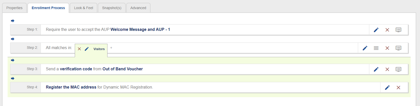
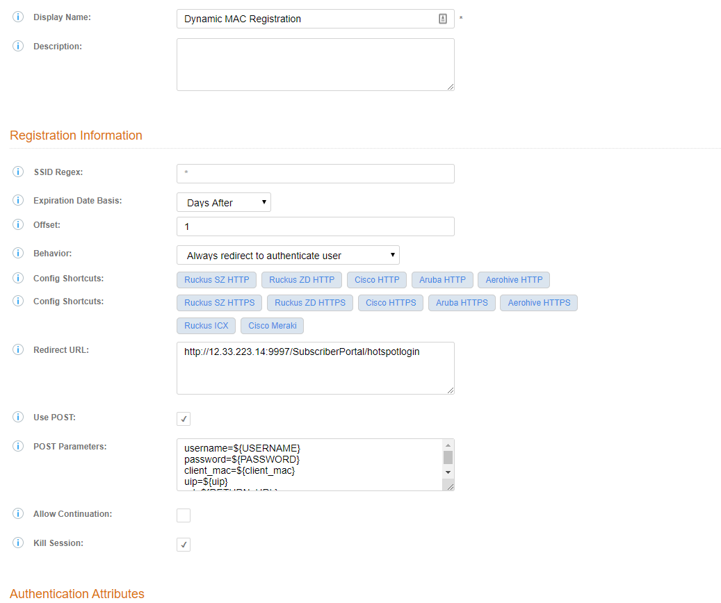
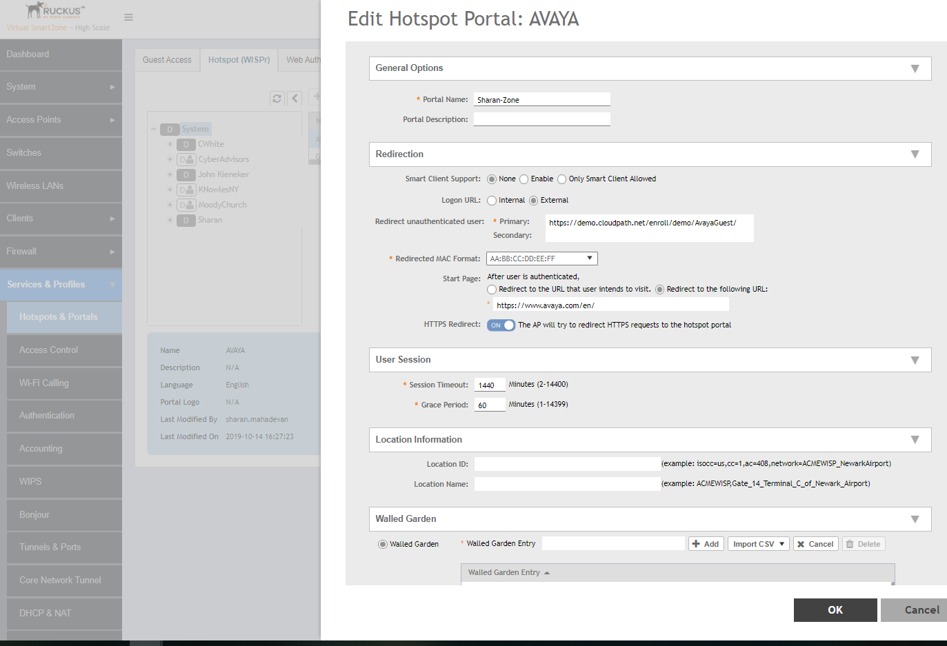
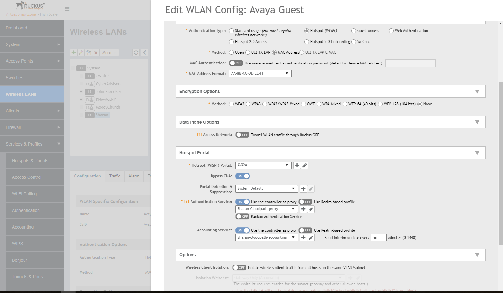
Sample configuration for guest users to use a hotspot WISPr portal for onboarding and remain on the same SSID after registering the MAC address.
I used “out of band voucher” to authenticate users, which uses one-time passcode delivered via email or text. You can also do front-desk vouchers or sponsor approval instead.
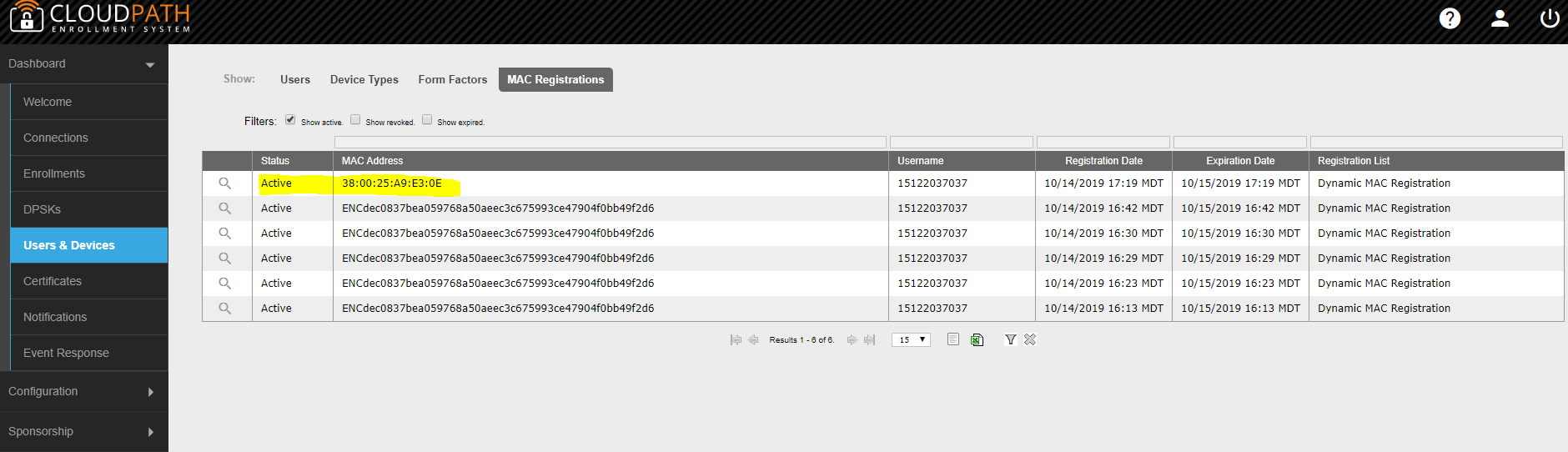
First step you need to do on SmartZone is to disable “Encrypted MAC Address”. By default, the MAC addresses are encrypted and it will break the redirect. Please SSH into your SmartZone and run the below command.
# config
(config)# no encrypt-mac-ip
Here is a before and after on Cloudpath’s MAC registration list. As you can see from my current MAC user list, it didn’t work until I ran that command.
In Wi-Fi, the client devices always makes the final roaming decision instead of Access Points. The roaming decision of each client varies according to the manufacturer’s proprietary algorithm, which is usually confidential. However, a few manufacturers have published the key factors that their devices consider before roaming to another access point.
Received Signal Strength Indicator (RSSI)
Signal-To-Noise Ratio (SNR)
Missed Beacons
Other factors include data rates, frame retries and CRC errors
Roaming Trigger Threshold
The minimum RSSI or SNR that they maintain with the current AP before roaming to another AP is called ‘Trigger Threshold‘.
Though you can influence the client devices to make a better roaming decision by increasing the minimum BSS rate to 12/24 Mbps and enabling OFDM-only mode, some client devices may still be sticky due to their algorithm. Ruckus has an optional feature called “SmartRoam” that allows the AP to force the client to roam by deauthenticating it and allowing it to find a better AP. This feature can only be enabled from the CLI.
When you enable this feature, the Ruckus APs monitor the uplink RSSI of associated clients and maintain a counter of number of frames below a specified low RSSI threshold. If a client is marked as sticky by the client, the AP will send a DeAuth frame with reason code 3. To avoid associating to the same AP that disconnected the client, it will also ignore the probe request and association request for a few seconds until the client find a better AP nearby.
If you determine that SmartRoam is ideal for your environment, you need to enable it on a per-SSID-basis from the CLI. You have to set a scale factor, which matches to the RSSI threshold. Default value when you enable SmartRoam is scale factor 1. It is not recommend to configure anything over scale factor 5. I recommend you to set a conservative value like 2 and test it.
RSSI threshold (dB)
Scale Factor (#)
5
1
10
2
15
3
17
4
20
5
23
6
27
7
32
8
40
9
60
10
My testing with scale factor 5 dropped a few frames due to the deauthentication/new association process and my WebEx/Teams/Zoom calls dropped or disconnected briefly during the roaming. So, I do not recommend it for roaming where voice over wifi or video calls are involved. If Band-steering is configured, the 5 GHz radios of the target AP will delay the probe response and SmartRoam of the original AP will also delay the probe response, which may leave the client device stranded for a few seconds. Some client devices may not automatically join the SSID if it receives deauth packets. So, caution has to be taken before enabling this feature.
As the recent COVID-19 situation has increased the need for temporary networks for pop-up hospitals, drive-through patient testing, and students without internet access at home, I would like to show the quick setup of a temporary network using Ruckus M510 LTE backhaul access point.
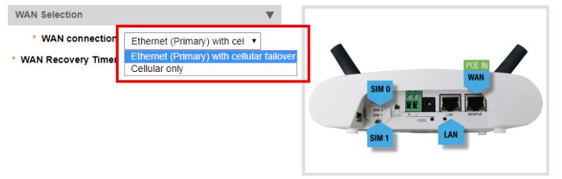
Ruckus M510 can work with one or two sim cards. In most use cases, one sim card is enough. You can also choose cellular as the only backhaul method or use ethernet as primary backhaul with cellular as a failover. In my case, I use cellular as the only backhaul with one sim card.
M510 can be managed through SmartZone controller or Unleashed. If you use the Unleashed model, there is no annual subscription fee or AP license cost. You can connect up to 50 APs and 1,024 concurrent clients using the Gateway mode (AP performs NAT and DHCP) of Unleashed. If you have an external router to do NAT and DHCP, you can connect up to 128 APs and 2,048 concurrent clients.
LTE Support
M510 is certified to work with AT&T network. It supports LTE FDD band B2/B4/B12 and WCDMA bands B2/B4/B5.
You can also use sim cards from any mobile virtual network operators (MVNOs) like Cricket Wireless powered by AT&T.
I love Google Fi as they offer data-only sim cards, if you have an active phone service with them. You can get up to 4 data-only sim cards per account. They don’t charge any monthly line access fee for those sim cards and you pay only for the data you use. For instance, you’ll pay $10 for each GB of data you use and it will be free after 10 GB for an account with 2 phone lines.
1 x 902-1169-US00 (This is the 12V DC power adapter. You can also use a PoE switch or injector)
1 x compatible Sim Card from AT&T, T-Mobile, or their MVNOs. If you don’t have a Micro-SIM, you can get a SIM adapter to convert a nano-SIM to Micro-SIM.
Prerequisite
Every cell phone carrier requires you to enter an unique Access Point Name (APN) settings that is required to establish a handshake between the carrier and your AP. Here is the list of a few APNs. You can contact your carrier to find this.
T-Mobile – fast.t-mobile.com
Google Fi – h2g2
AT&T – broadband
Set-Up
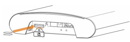
Plug an activated SIM card into the primary slot and power on the AP.
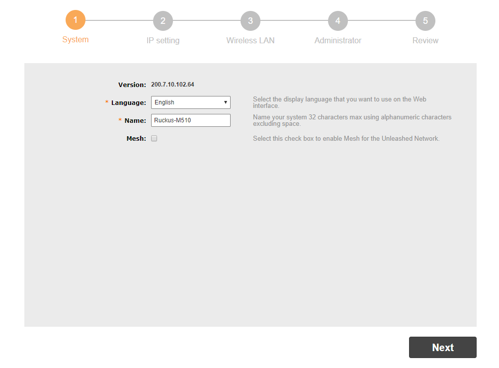
In this setup, I’m using a browser-based setup. You can also use Ruckus Unleashed App to set it up. The AP will broadcast a temporary unencrypted SSID named “Configure.Me-[xxxxxx]”. Connect your laptop or phone to this SSID and launch a web browser. Enter “unleashed.ruckuswireless.com” on the browser and press enter. It will redirect you to the setup wizard shown below.
If you don’t want to configure it via Wi-Fi, you can also plug-in an ethernet cable into the LAN port of the AP and the other end into your laptop. In this case, you’ll need to set your laptop adapter with 192.168.0.x/24. AP’s default management IP is 192.168.0.1.
Choose your language and give a name for the AP.
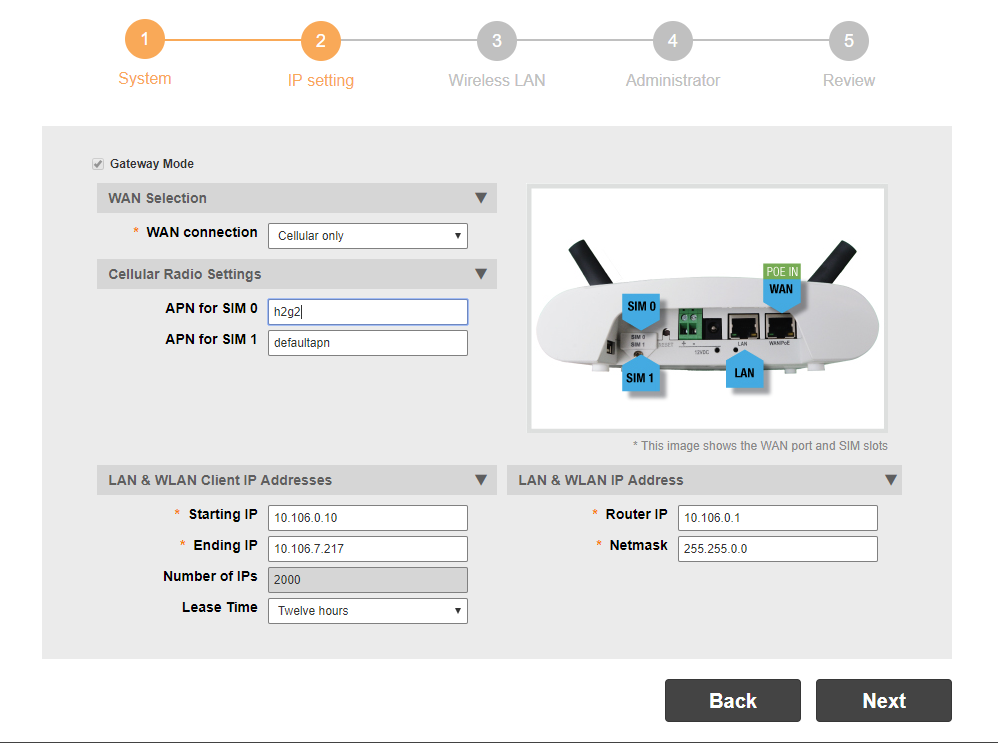
In the next step, Choose ‘gateway mode’ as this mode enables the AP to perform DHCP and NAT without an external router or modem. You’ll need to enter the APN settings of the carrier. In my case, I used Google Fi’s APN “h2g2”.
Choose ‘cellular only’, if you’re setting up a temporary network without ethernet access. As we choose the gateway mode, you can configure your DHCP server settings. I went with the default settings using 10.106.0.0/16 network.
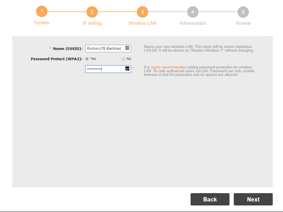
In the next step, you will be asked to create your first Wi-Fi SSID. You can configure advanced settings after the setup wizard is completed.
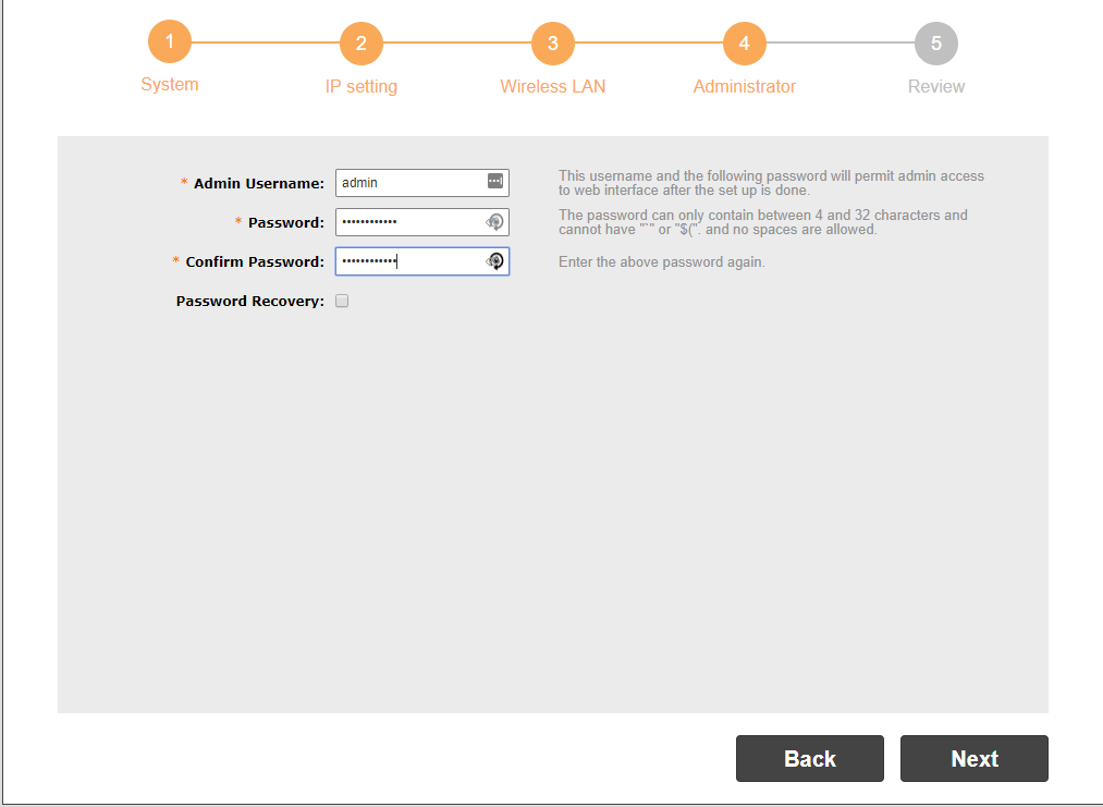
This is the last step of your wizard and you need to setup the admin credentials.
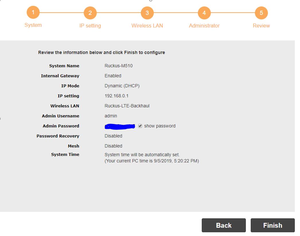
Review your settings and you have completed the basic setup. After you click finish, the AP will reboot and will come back online in a couple of minutes.
You can connect your client devices to the SSID you created. You can use your Ruckus unleashed app or use your browser to AP’s management IP address to perform advanced setup. The Unleashed app will also allow you to manage this network remotely from anywhere.
This is a typical setup for Managed Service Providers (MSPs) managing remote access points, where the SmartZone controller is configured with a private IP address and is behind a NAT/Firewall. As the COVID-19 situation has forced a lot of employers to adapt to employees working from home, this setup is also applicable managing remote APs of their SOHO employees from a central controller. Remote employees will also usually need access to corporate SSIDs and I’ll cover data tunneling in a separate blog post to cover that.
In most of these deployments, the remote APs are usually are also assigned with private IP addresses and are behind a NAT/Firewall.
Design:
In this setup, a virtual or hardware SmartZone controller at the corporate site is setup with a single interface setup (one IP address for control, cluster, and management traffic). For advanced setup, you can setup your controller with 3 different interfaces, which is not covered in this post.
Corporate Site
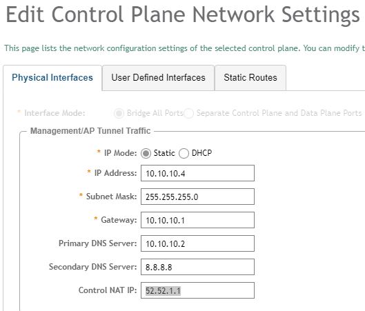
Private IP address of the SmartZone – 10.10.10.4 (any static IP configured by the admin)
Public IP address of the NAT gateway – 52.52.1.1 (any static IP assigned by ISP)
You may also use the dynamic IP assigned by your ISP and use a dynamic DNS to keep track of the changes.
Remote Site
Private IP address of the remote AP – Any private IP assigned by the DHCP server
This post assumes that the remote site is a home office that doesn’t require any firewall modification or a remote branch office with the required firewall ports open.
Configuration Steps
Step 1 – Configure your SmartZone with the public IP address of the NAT gateway
As the controller is only aware of the private management IP address assigned during setup, we need to make it aware of the public ip address that will be used for the control traffic between remote APs and the controller.
It can be either configured from the GUI or CLI
GUI: System -> Cluster -> Control Planes -> Configuration -> Configure
CLI: SSH in the controller’s management IP address and execute the below command
SZ-Primary# config
SZ-Primary(config)# ip control-nat 52.52.1.1
SZ-Primary(config)# exit
Do you want to update this context configuration(or input ‘no’ to cancel)?[yes/no]yes
Step 2: Configure your controller with LWAPP2SCG
This configuration is required for APs with older non-SmartZone firmware to discover the controller and upgrade to the right firmware.
SZ-Primary(config)# lwapp2scg
SZ-Primary(config)# policy accept-all
SZ-Primary(config)# exit
Do you want to update this context configuration(or input ‘no’ to cancel)?[yes/no]yes
You’re now done with the configuration on the controller side!! Rest of the changes need to be done on your NAT/Firewall.
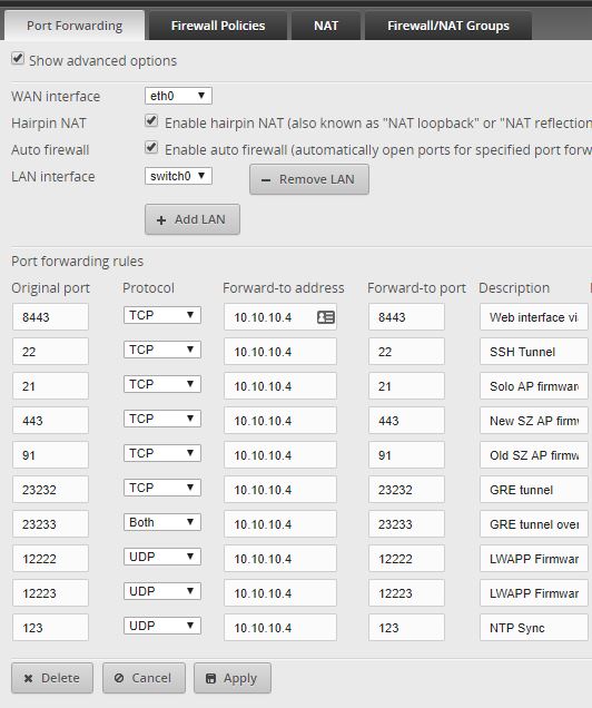
Step 3: Configure your NAT/Firewall to allow port forwarding
Here is a document describing the list of firewall ports required to be open – link
I use an Ubiquiti Edgerouter at my home lab as my NAT gateway and here is a screenshot of the ports being forwarded. As I enabled auto firewall on my edgerouter, it automatically creates the corresponding firewall rules. In your setup, you may have to do both.
This completes the setup at the corporate site. Depending on how complex your network is, you may have to do additional changes to your firewall and NAT. If you want to allow AAA authentication or WISPr portals, there are additional ports that are required to be opened.
Step 4: Use DHCP option 43, DNS entry, or static entry at your remote site to point to the controller
Once the AP knows the controller’s public IP address using one of the supported controller discovery methods (DHCP, DNS, CLI command), the AP will be connected to the controller, perform a firmware upgrade, and will be online after 10 minutes.
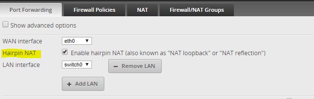
Step 5: Use NAT reflection for allowing APs inside corporate NAT to communicate with the controller
The SmartZone is configured to use the corporate NAT’s public IP address for AP communications (control NAT IP). However, some of the APs are on the same LAN. They will also receive the control NAT IP, which is the NAT gateway’s IP. Normally, the AP would not be able to communicate with the SmartZone without additional configuration on the NAT device. NAT reflection configuration is required to allow the APs inside the NAT to communicate with the SmartZone via the NAT device’s public IP address.
NAT reflection is also called as ‘Hairpin NAT’ in some NAT gateways. Here is the setting on my Edgerouter.
This completes the configuration. I’ll explain tunneling configuration in the next blog.
Knowing the Tx power of an AP is very important for predictive designs and also for engineers who like to manually configure it to match the Tx power of client devices. As Ruckus doesn’t let you configure the absolute Tx power, this post shows how to find it.
Let’s start with the basics. We should know the difference between an Intentional Radiator (IR) and Equivalent Isotropically Radiated Power (EIRP) to understand how a Wi-Fi manufacturer determines the maximum allowed Tx power of an AP in a country.
Intentional Radiator (IR)
As per FCC, an Intentional Radiator (defined in Section 15.3 (o)) is a device that intentionally generates and emits radio frequency energy by radiation or induction that may be operated without an individual license. The IR consists of the components inside your access point that generates the RF before passing it on the antenna.
When you set the Tx power in your management console (like Unleashed or Cloud), you’re configuring the Tx power before the AP passes it on the antenna and this is called as “conducted power”.
Max Conducted Power allowed by FCC on Access Points
2.4 GHz – 30 dBm
5 GHz – 30 dBm
Though 30 dBm is allowed to be transmitted from the AP, the manufacturer allowed power could vary based on the model of access point you have. Entry-level APs usually have lower maximum Tx power than high-end APs. You need to keep this mind when setting a zone or venue-level Tx power settings as you might have different AP models in the same venue. A 3 dB reduction of power on one AP model could set your conducted power as low as 13 dBm (H510) vs. another model at 20 dBm (R510).
The conducted power also varies based on the frequency and channel the AP chooses. For instance, H510 has 16 dBm as max. Tx power in 2.4 GHz and 19 dBm as the maximum Tx. power in 5 GHz.
Note – the Tx power listed on data sheets is the generic max power of the AP and it doesn’t show the actual reduced power that is applicable as per FCC rules in US. If you want to know the max Tx power of an AP allowed in US, you can reach out to your Ruckus SE.
Equivalent Isotropically Radiated Power (EIRP)
EIRP is the Tx power from IR combined with the antenna gain after any loss due to signal attenuation in the connection cable between the transmitter and antenna. So, EIRP of your Ruckus AP is the combined value of the configured Tx power and the antenna gain (assuming minimal loss between transmitter and antenna).
EIRP (dBm) = Conducted Power (dBm) + Antenna Gain (dBi) – Cable loss (dB)
Max EIRP allowed by FCC on Access Points
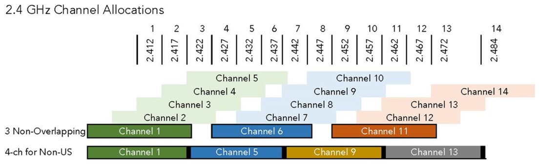
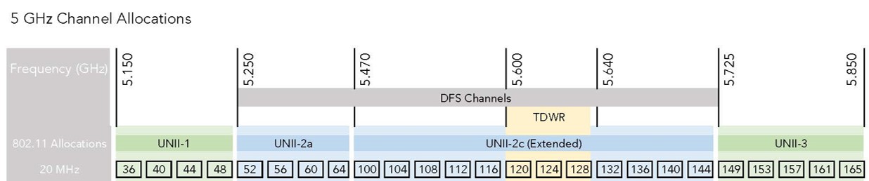
2.4 GHz Channels 1 – 11 (36 dBm)
5 GHz U-NII-1 channels 36 – 48 (36 dBm)
5 GHz U-NII-2A channels 52 – 64 (30 dBm)
5 GHz U-NII-2C channels 100 – 144 (30 dBm)
5 GHz U-NII-3 channels 149 – 165 (36 dBm)
Image Source – Wireless LAN Professionals
Antenna Gain
This is where Ruckus shines with the Beamflex gain. Beamflex adaptive antenna will get you approx. 3 dBi gain per 2 radio chains on most models. This will be added to the conductive power you set on the management interface and will make sure the EIRP is less than the FCC limit.
How to find the conducted power of your Ruckus Unleashed AP?
SSH to the Unleashed master AP’s CLI and execute the below command:
ruckus> en
ruckus# debug
ruckus(debug)# rksap_cli -A -s “iwconfig”
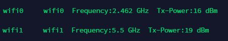
Here is the output of my H510 wallplate AP currently configured with maximum Tx power. It shows 2.4 GHz using Tx power as 16 dBm and 5 GHz at 19 dBm.
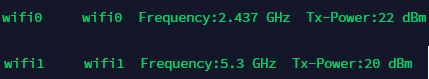
My R710 shows 2.4 GHz at 22 dBm and 5 GHz at 20 dBm.
How to find the conducted power of your Ruckus SmartZone AP?
If you want to find the same Tx information in SZ-managed APs, you will need to access the shell mode of the AP and execute the below command: